Building a 6502 Computer, Part 8: Flash Drive
Storage for the KiT: 256 whole kilobytes!
I attended Open Sauce at San Francisco recently, which was such a blast and inspired me to get back into these posts. I was primarily there to support the Novoloom booth—but I did bring the KiT and was able to to thank Ben Eater for starting this project off! I have four upcoming posts planned to catch up to the current state of the KiT, covering the flash drive, sound card, (partial) C compiler, and the current software library.
So, the flash drive. If you’ve followed the project this far, you might know that I’ve described two ways to get a program onto the KiT: flash the EEPROM and include the program there, or load it over the UART. But this means there isn’t a nice way to quickly switch between different programs (say, if I want to show someone all the software I’ve written), since not everything can fit on the ROM and flashing it is a bit annoying. The solution? Persistent writable storage! In 1980, this would have likely taken the form of a floppy drive or a tape drive. But these are pretty bulky, slow, and inconvenient options (and my desire to experience 1980s computing only extends so far). So, I decided to go with something a bit more convenient: a flash drive.
I picked the SST39SF020A 256KB flash chip, as it comes in a DIP package and would provide plenty of storage for my needs. I had to tweak the address space a bit to fit in enough space for accessing the flash storage and settled on the following layout where I’d be able to access to flash chip (aka the SSD) 4KB at a time:
Memory map:
0000-5FFF: RAM (24KB)
6000-77FF: VRAM (6KB)
7800-7FFF: I/O (2KB)
    7800-78FF: VIA 1 (256B)
    7900-79FF: VIA 2 (256B)
    7A00-7AFF: UART (256B)
8000-8FFF: SSD (4KB, banked)
9000-FFFF: ROM (28KB)
This is especially convenient as the flash chip is organized into 4KB sectors. To write data to the flash memory, you first need to wipe the sector you want to write to and then write one byte at a time to the wiped sector. By using a very simple filesystem that allows each sector to hold only one file, this makes managing storage easy: I can store up to 64 4KB files, one per sector. This is enough to store most programs I’ve worked on, and I can always have a file span multiple sectors if needed. Here’s the very simple spec for the file system, which allows storing a file type, file name, and checksum, among other metadata:
KiT Simple Filesystem (KSF)

64 file slots, one in each of the 64 4Kb sectors of the 256 Kb SSD.
Each file can be up to 3842 bytes (4Kb minus one 256-byte header page)
Page $80 is the header page; a file is stored in pages $81-$8F.

Header page spec:

Bytes | Contents
-----------------------------------------------------------------
00    | Always $00 to indicate this sector is occupied
01    | File type ($00 = program, $10  = image)
02-03 | Start address (lo, hi)
04-05 | File size in bytes
06-07 | Fletcher checksum of file (lo, hi)
08.   | Next sector (for multi-sector files; $ff if no next sector)
09.   | Video mode (for images, $ff for programs)
10-1F | Filename (up to 16 ASCII chars, null terminated)
20    | Always $00


File types:
$00: program
$10: image
$20: data
To control which sector is accessed, I’m using VIA 2 port B (aka port D), which is connected to the KiT 2 expansion slots 2-5. I picked slot 2 for the SSD and updated the GAL that sends slot select signals to activate slot 2 when the address range $8000-$8FFF is accessed, but only when the clock (PHI2) is high, which ensures the write timing is correct. (See the KiT 2 post for more details about VIA 2 and the slot GAL). Here’s what the circuit diagram looks like for the SSD expansion card:
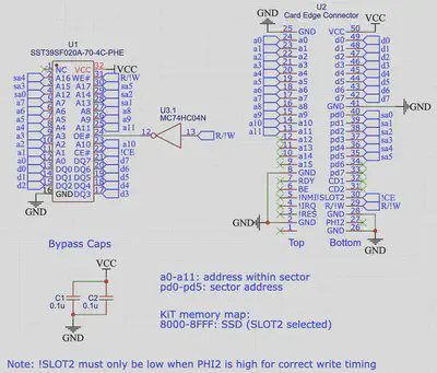
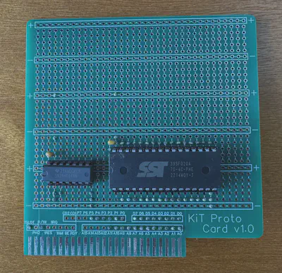
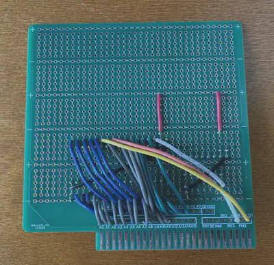
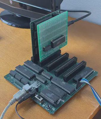
By hooking up port D to address bits 12-17 of the flash chip, this selects one of the 64 sectors, while the KiT address bus lines 0-11 select the address within the sector. Address bus lines 12-15 are the ones that the slot GAL uses to select slot 2, which activates the chip enable line on the flash chip. That’s all there is to it! The only slightly annoying complication is that the flash chip has separate active-low write enable (WE#) and output enable (OE#) pins, so I needed to add a not gate to invert the read/write line (R/W!). Here’s what the SSD looks like on a prototyping expansion card:
| Front | Back |
|---|---|
 |
 |
And installed in the KiT 2:
I added some commands to the KiT operating system to interact with the SSD:
Dxx: Directory. Displays a list of files saved to the SSD, starting at sector xx (default: 00).
Cxx: seCtor. Set the active sector to xx.
Exx: Erase. Erases sector xx.
Fxx: File. Opens the file in sector xx.
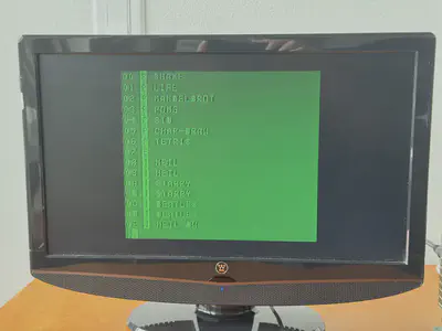
The File command behaves differently depending on the file type stored in the header. For programs, it copies the program to RAM at the stored start address and jumps to the start address, running the program. For images, it loads them into VRAM and sets the video mode as specified in the header, displaying the image. In addition, I modified the UART Load command to provide an option to save the loaded program or image onto the SSD at a specified sector with a specified file name. Here’s the output of Directory running on my KiT emulator:
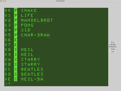
You can see the sector number, file type (Program, Empty, Image), and file name. And here’s the real thing!
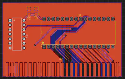
I’ve also designed a little PCB for the SSD, but the prototype works so well that I don’t know if I’ll bother to get it manufactured. Perhaps someday.
The SSD is a simple little expansion card, but it makes the KiT 2 so much more usable. If you’re curious to see how the flash chip commands are handled in assembly, here’s my code: ssd.lib.
In the next post (whenever I get around to it): the sound card!
Previous post: Part 7
Kiran Tomlinson
Senior Researcher
I’m a Senior Researcher at Microsoft Research in the AI Interaction and Learning group.